
S.S. OLYMPIC – S.S. TITANIC – S.S. BRITANNIC ![]()
Sources
All the images are provided by the courtesy of National Museums NI, the Harland & Wolff Collection (www.nmni.com)
- Ship No. 400 Olympic. Ship No. 401 Titanic | Explore Our Collections (nationalmuseumsni.org)
- Ship No. 335 Celtic | Explore Our Collections (nationalmuseumsni.org)
- Ship No. 335 Celtic | Explore Our Collections (nationalmuseumsni.org)
From my collection
Drawing ”No.433 – Tank Sections”
Understanding the joints
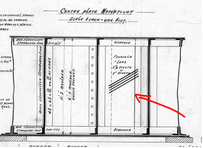
This article will try to clarify how the joints of the vertical keel were designed and assembled. There are many pictures of how the joints look when assembled but there is no clear information of how the joint is made. From what we can see in the drawing: No 433 – TANK SECTIONS the joints overlap each-other from 14” to 16” with the top and bottom being scarphed to make a flat surface for the bottom and top bars
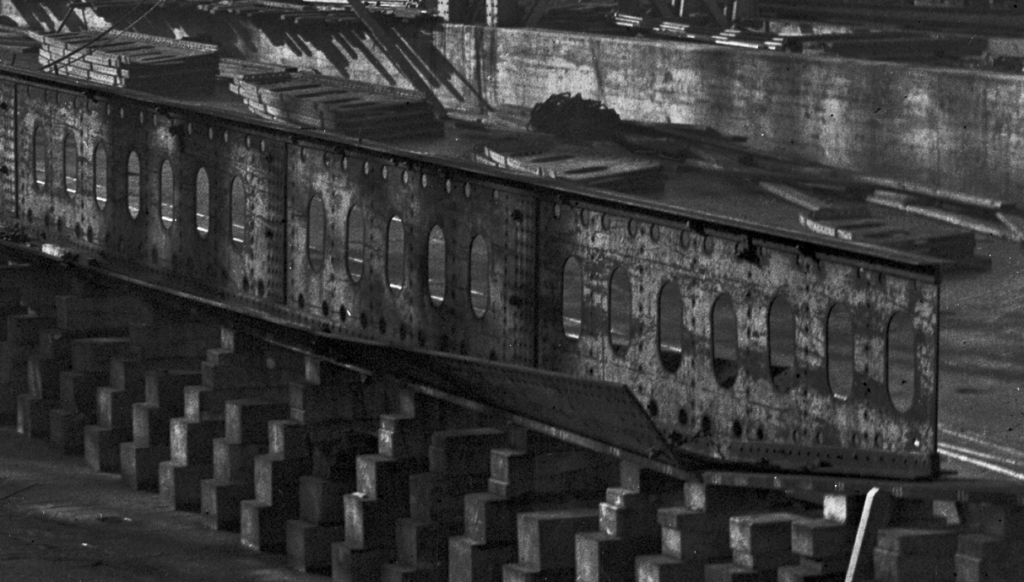
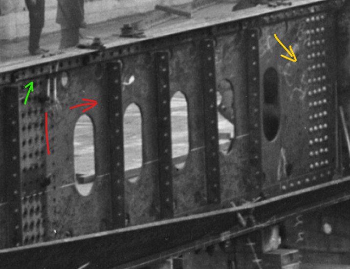
To understand how these joints are made we must look for photographs that can show us some information about them. Below is an image from when Olympic was built where we can see the joints.
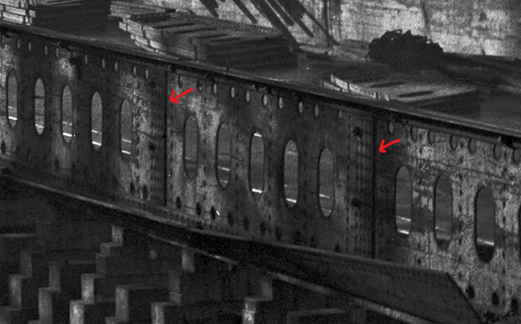
If we zoom in on the photograph, we can see that on the port side the overlap joint is facing backward towards the stern. If you look closely, you can also see a bit of the scarphed area, marked in green.
If we look at the starboard side, we can see that the joint is facing forward instead, this is because you can’t see the end of the joints (red marking), and so the same can be seen for the scarphed area.
From here we must look elsewhere since there it not a lot of photographs on these joints on the Olympic class liners. Instead, we will have a look at the Celtic (No. 335) that was built during the years of 1899-1901.
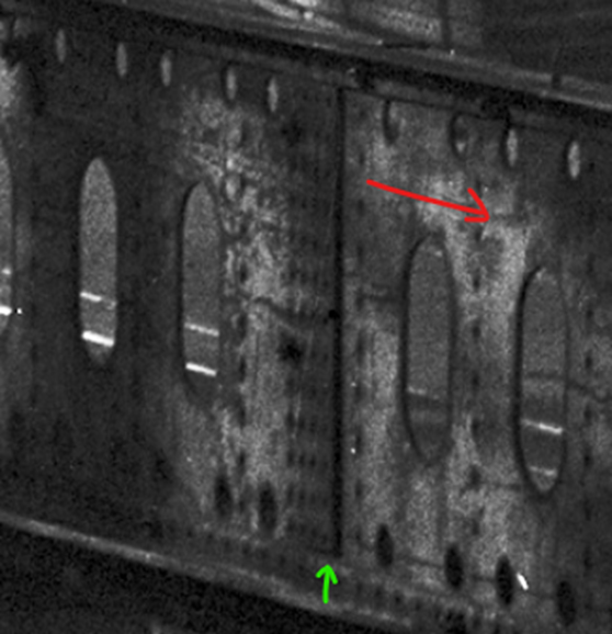
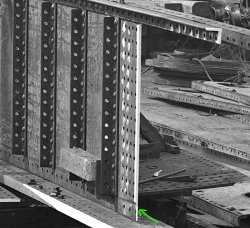
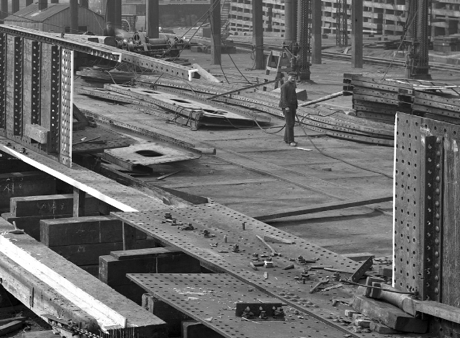
Below you is a photograph from NMNI (H768 and H767) that shows the joints very well, this is the best photograph we know of so far, the scarphed area is marked in green here as well.
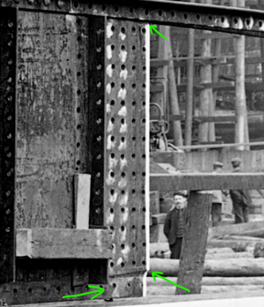
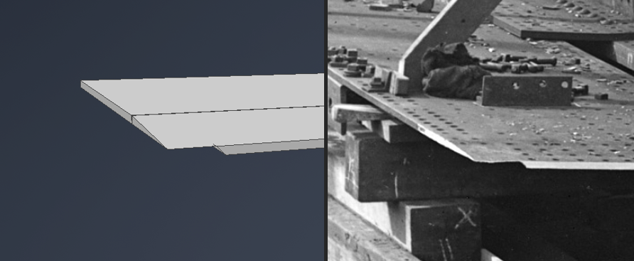
To get a better understanding of how the joints really look like, we can zoom into another area of photograph H767. There we can see that the scarphed area is very thin at the end of the plate. Since we can see the method for scarphing that is used in these applications we could assume that the same method is used elsewhere, and that vertical keel plate also use this method.
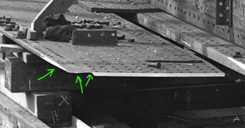
If we also look at another section of the photograph H767 we can see a plate that has the same design that will join the plate in the photograph above. If you look closely to the plate, you can see a slight bend line on the plate, marked with yellow.
Recreating the joints in 3D
Now when we know how the joints are made it’s time to try to recreate them to see if we can make them look like the photograph.
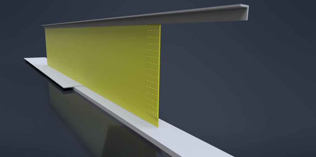
We start with a plate with a thickness of 20/20” which a common thickness of plates on No.433, thereafter we make a bend line 16” from the edge.
We bend it with an angel of 3,6 degrees (just so the face of the plate gets in line with corner of the joining plate)
Now it’s time to add the scarphed area of the joint. To do this we use the height of the bottom or top bars (for this example we will use 5”) and cut away the material. The shape of the scaphed area could also be discussed but this is just a principal assumption based on the images we have seen in this article.
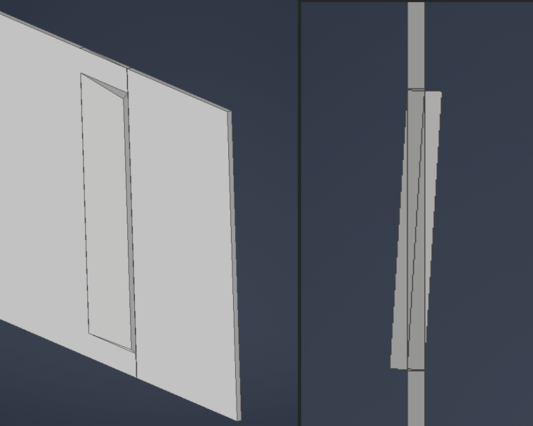
Now when we have bent and scarphed the plate it’s time to see the result and compare it to the scarphed plate in the image H767. As you can see it looks very similar.
If we join the plates together to see what it looks like when they are assembled, we can also see that we have achieved the design we are looking for.
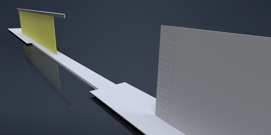
Port side has the joint facing backwards, while starboard has the joint facing forward with the bottom/top bars having a flat faces to be riveted against.
For another comparison I did a simple recreation of photograph H767 and you can see the result below.
Close-up of the joint
Conclusion
Since there is no technical documentation of the joints on the vertical keel, we must rely on photograph and draw our own conclusions about the design. From the photograph in this article, it’s a fair assumption that the joints of the Olympic class liners would have the design presented in this article in regard to the vertical keel joints. The illustrations are only a principle of the design and should not be taken as fact.
To get my design confirmed, I have posted pictures and drawings on the anchor in various Facebook groups, consisting of many members who has good knowledge about Titanic, Olympic and Britannic.
If new information / drawings get presented I will update this article to accommodate those changes. Article and 3D images are made by Joakim Amundsson