
This articles focus is mainly on the TITANIC Center Anchor
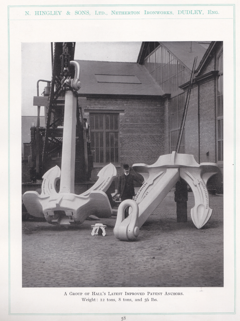
S.S. OLYMPIC – S.S. TITANIC – S.S. BRITANNIC ![]()
Introduction
This article will be about my studies regarding the center anchor of the Olympic (mainly Titanic) class. During the autumn 2020, I studied all available material that I found with help of the book Titanic The Ship Magnificent Vol 1 (will be referred to as TTSM from now on), The studie from ”University of Warwick, N. Hingley & Sons Limited – Black Country Anchor Smith and Chain Cable Maker”, The Facebook groups ”Titanic Tech” and ”RMS Titanic Model Research and Tech” as well as other images and data found on Google. This article is written in Swedish and translated into English.
Sources
Titanic The Ship Magnificent Vol 1 (TTSM), pages 459-470
University of Warwick – N. Hingley & Sons Limited – Black Country Anchor Smith and Chain Cable Maker [http://go.warwick.ac.uk/wrap/36367]
Images
Images are referenced as figures with page numbers followed by the order the figure is shown. Page 1, figure 1 becomes [1.1], the next figure on page 1 is [1.2]. I do not own the rights to any images in this article, apart from my own 3d generated images, the images in the article are used as “fair use”. If the owners of the pictures in the article wants me to remove images from this article, please contact me. Contact information can be found at the end of the article.
Background
The reason for this article is that I was about to make a 3D model of the center anchor for the Titanic, and the only information I could get came from TTSM; there were two approximate measurements of height and width. The 3D model’s shape and size is based on these measurements.
There are of course plenty of pictures on the anchor but none that speaks of dimensions or shape. The dimensions given from the book are 7ft long and 10ft 3in wide, these measurements are approximate.
I do not not know where these measurements come from, but I must assume that these are correct. To be sure, I will check if these measurements are correct by comparing them against the anchor well in which the anchor is intended to be mounted on the vessel.
To check this, I use copies of Britannic’s original drawings, these drawings are used to check other drawings that contain theoretical dimensions of the anchor.
Below is a part of the original drawings for Britannic (No.433)
Page 2 of 20
Comparison
When you look at the width, there is only one place that you can measure, but when it comes to length, there are some question marks. Is it measured from the bottom to the top of the anchor or from the bottom to the mandatory shackle, that must be mounted to allow the anchor to be free articulated?
I started by measuring the anchor well show in figure 2.1. Between each frame member, like 148F and 149F, there are 24 in we know this from page 69 in TTSM. I calibrate the drawings according to that measurement; I then obtain measurements according to the figure below.
The next drawing is from Oskari Syynimaa and is scaled according to the same principle, and there you get similar values as in previous drawings. Since the drawings on the ship are “fixed”, and the anchor has a shape that is unclear, I believe that the geometry of the ship indicates the size of the anchor and not the other way around.
Page 3 of 20
Adaptions
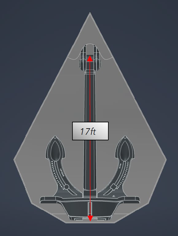
What you can see in these two sketches is that the total length including the shackle could be about 17ft 6in, which very well falls within TTSM dimensions. I have tested this by creating the model with measurements taken from different reference points and concluded that Oskari’s sketch is the one that fits best in the anchor well of the vessel. Figure 4.1 shows that if the anchor without the shackle would measure 17ft, there would not be room for the shackle. Conclusion: It should be shorter.
When the anchor is then resized to Oskari’s dimensions, the fit to the anchor well looks much better, and there is room for both the anchor and the shackle, see figure 4.2.
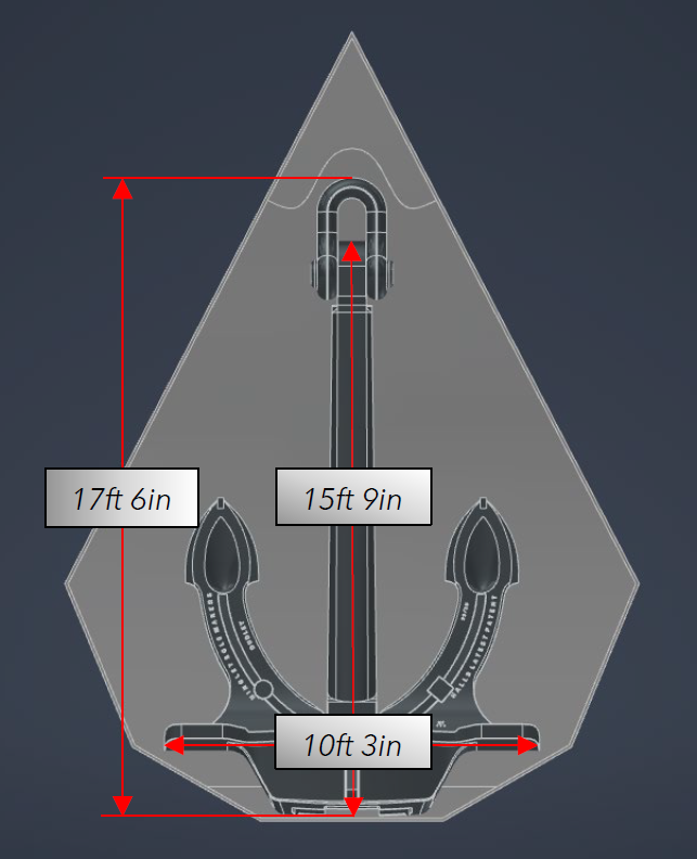
These are the dimensions I will go with. I use the provided width measurement from the TTSM, and the length from Oskari’s drawing. Since I cannot confirm these measurements, this I my interpretation of the sketches and drawings.
Page 4 of 20
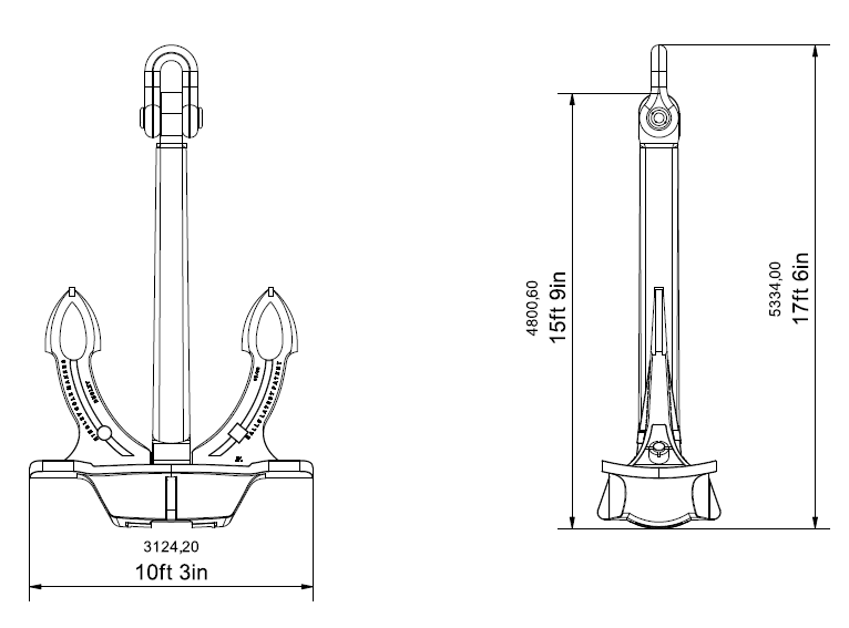
Now that we have established a width and length we can move on. I have put in these new measurements in a simple drawing of my 3d model as shown below in figure 5.1.
First glance
The first glimpse of the anchor’s design comes from a sketch in TTSM and is certainly recognized by many. I started by drawing an overlay to this image in Adobe Illustrator and tried to make a 3D model of it. But the anchor turned out to be much more complex and advanced than I initially thought.
The figure above shows a correct sketch of the Titanic’s center anchor but does not reveal much more than the shape itself. Dimensions are missing and we do not know if it has the right proportions. So I gave up the idea to base my model on this sketch, and continued to look for other drawings and dimensions, my findings have however been checked against this sketch.
Page 5 of 20
My findings
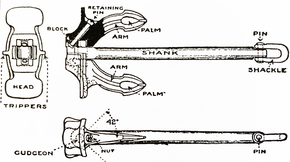
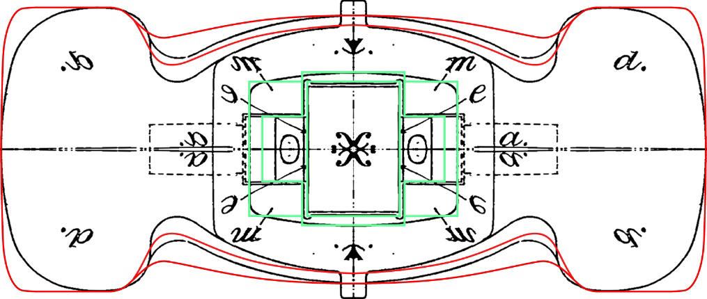
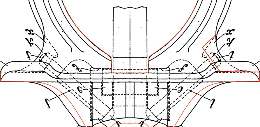
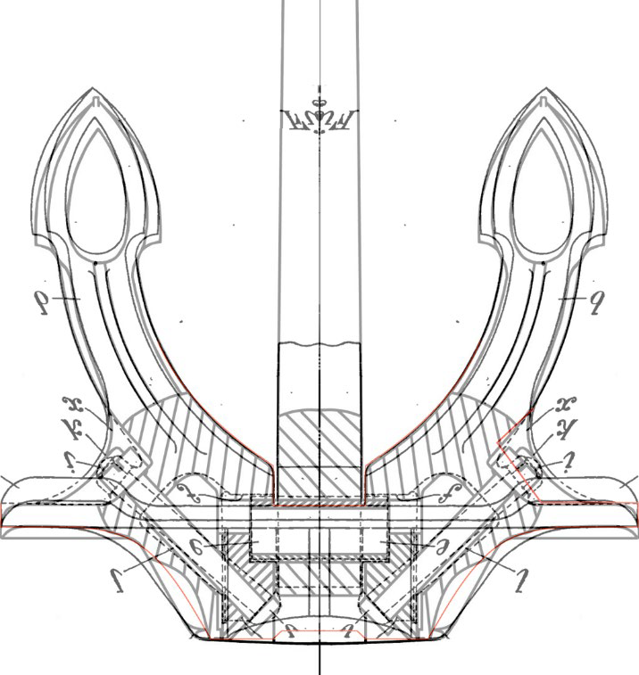
Later I found a study from the University of Warwick that contained a few different sketches through the years 1886-1917 and on pages 375-376 in this rapport there is a sketch that is very similar to the sketch from TTSM, the sketch was splitted to two pages, I combined the two pages of into one image. See figure below.
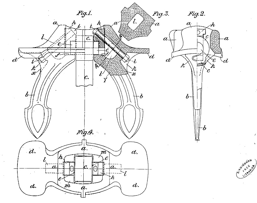
Unfortunately, I cannot confirm if this is a drawing from Hingley & Son’s but the drawing is from 1906 and is as mentioned very similar to the original sketch, and reflects very well how anchors of this type are built. With the help of this sketch I have learned a lot about how this type of anchor is constructed.
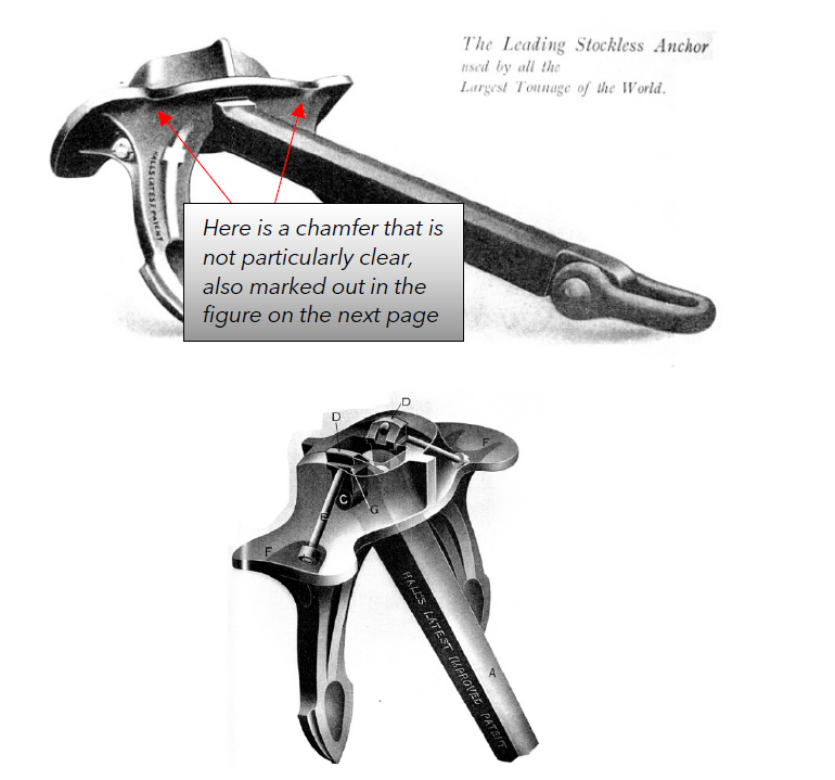
In the same report, there are also more images of this type of anchor, and some of these images show in a different way how anchors of this type were put together, what parts they consist of and the name of them.
Below are images from the article from the University of Warwick as before referenced.
Page 6 of 20
My discoveries
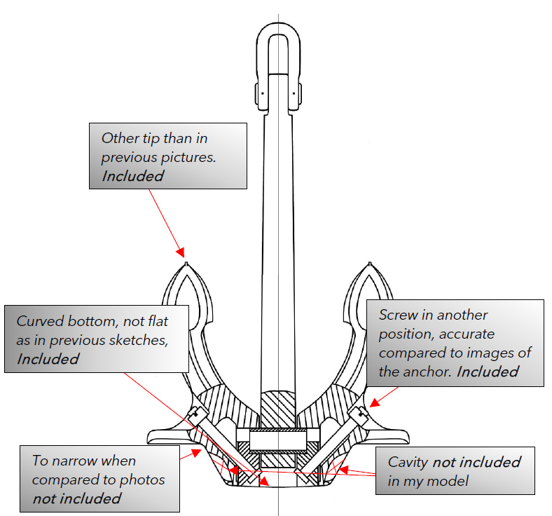
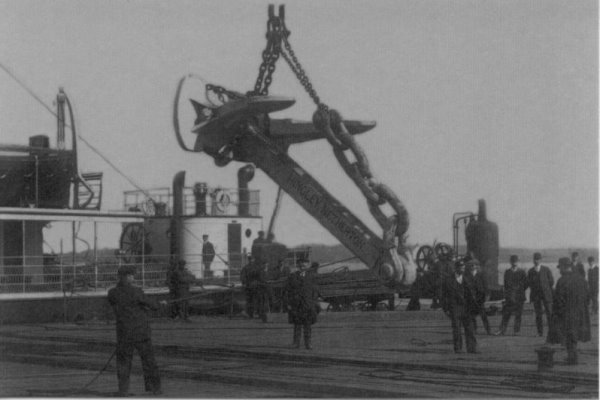
While I have studied images and different types of drawings, some of these images are included earlier in this article, I have encountered lots of deviations and questions that have come up due to image quality, camera angle and the anchor position on the images.
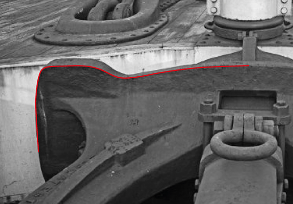
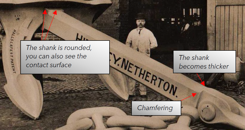
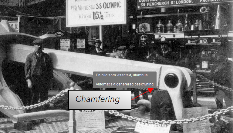
Below is an image from SS Olympic and it is by far the best picture available on the anchor at this angle. In the picture I have described what I have been unable to find in existing sketches or drawings.
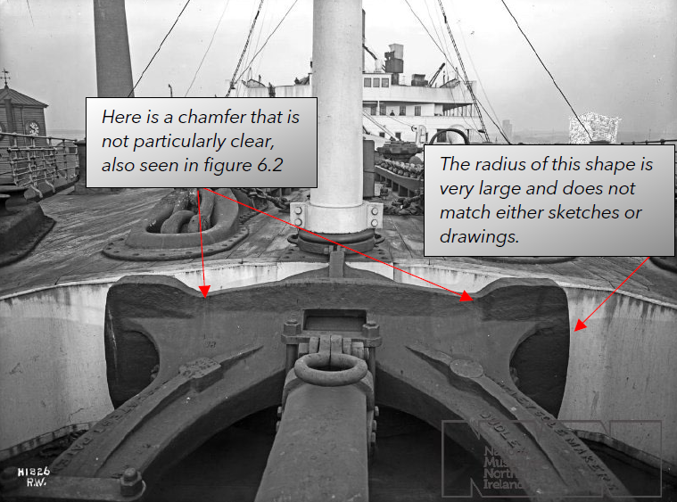
Below are other observations made while I was studying images on the anchors during the current time:
Page 7 of 20
Page 8 of 20
Below I have drawn lines on images that will then act as a reference line for my 3D model.
Reference sketches
After these observations, I have used figure 6.1 and added the new observations into my reference image, these together will be my base for the 3D model.
Page 9 of 20
The profile of the anchors comes from figure 6.1, I have added conture lines to better correspond to the shape of the anchor seen in the images. I have also tested making a model using the original 6.1 as reference and its shape does not become similar to images of the anchor.
Note: This will work as a base to the model, changes may occur during the modeling process to better correspond to images.
Size
What I have come to during my study, is that the only dimensions that are available are the dimensions specified in TTSM on page 460, which are stated earlier and shown in Figure 5.1, and a weight of 15.5 tonnes.
To get approximate measurements of the anchor, when making the model I have used the above measurements to scale images of the anchor to get measurements that can be close to what the actual measurements were, however you can not say that this method is reliable but it can be used to adjust the proportions of the anchor.
The steps I had to go through to get as accurate measurements as possible are as follows:
- Find a suitable image to apply the control measure.
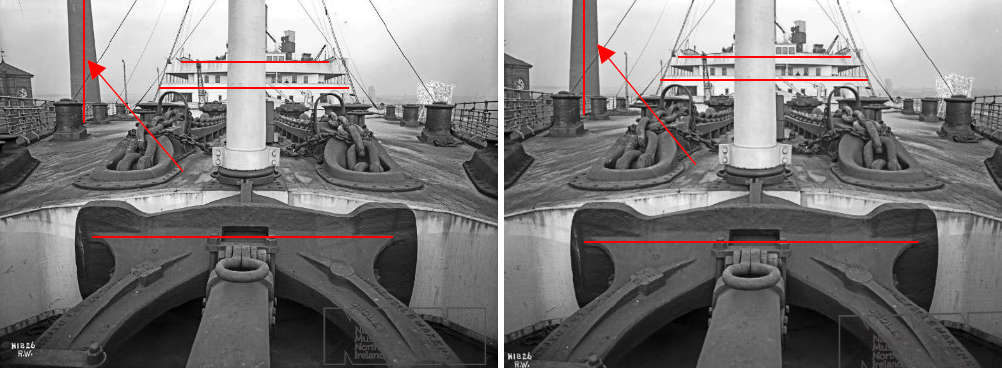
- Because the images gets a perspective when photographed, everything is slightly deformed, I try to corrected the images to get them as straight as possible.
- Imported the image into Sketchup to scale it to the correct size.
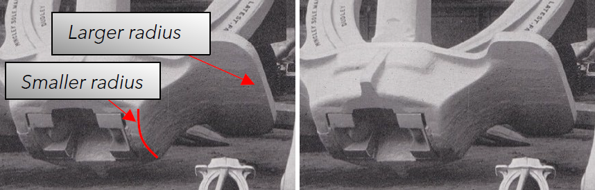
Below is an original image beside a corrected one:
Page 10 of 20
When the image is then loaded into Sketchup, I can scale it according to my reference measurement and use lines to measure other parts of the image. Figure 11.1 is a screenshot from Sketchup, I can now measure lines in the picture to get more measurements.
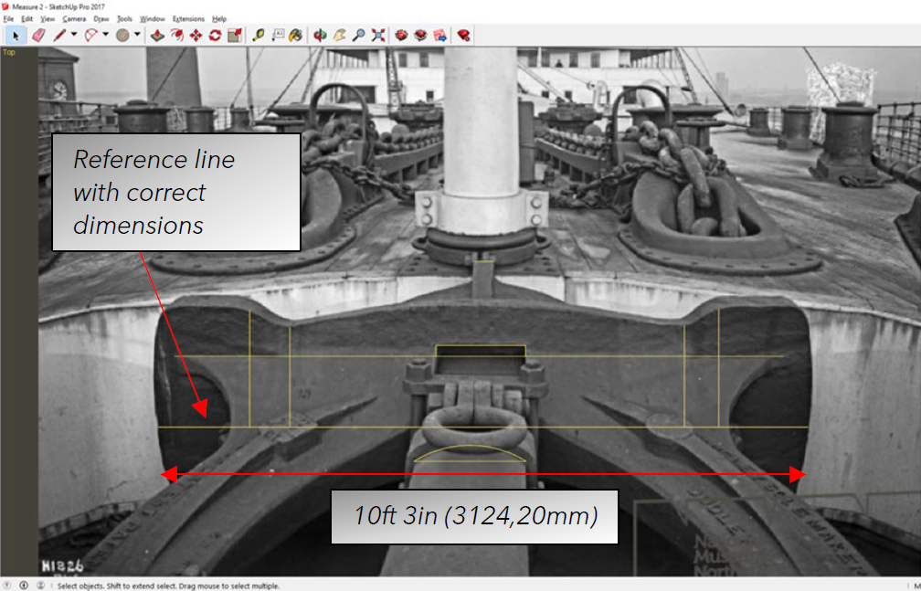
As mentioned earlier, this method is not particularly reliable, but it gives me a little more information about the proportions of the anchor which helps me to make the 3D model more accurate to the photos.
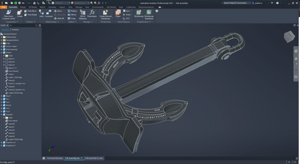
Completion
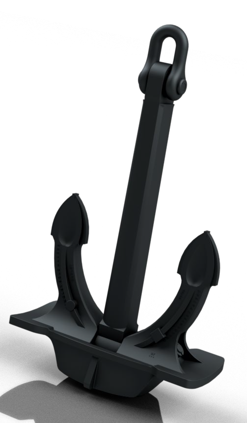
After I put pictures and measurements together, I have produced a model of the anchor which in my opinion is very similar to the original, and has a weight of about 15505,584 kg which is also very close. That gives me an indication that the design and shape are close to the original.
To get my design confirmed, I have posted pictures and drawings on the anchor in various Facebook groups, consisting of many members who has good knowledge about Titanic, Olympic and Britannic.
It did not take long before I received some answers and a new sketch of the anchor from a credible source which made me take in this sketch and redraw parts of the anchor. I have disregarded some parts of the sketch as the photo evidence shows that the sketch contains errors in my opinion, see figure 12.1
Page 11 of 20
New Sketch
I got the new sketch from Cyril Codus who is known in the Titanic, Olympic and Britannic communities. It shows great similarities to the figure 6.1. I did however find some different shapes in the new sketch which I decided to add into my model.
If you put the new sketch upon the old one, you see some differences, these are now implemented in the model and match the new sketch.
Internals and other proportions seem to align great. Bolts/rivets that hold the parts together have a different angle that corresponds better with reality and this is also implemented in the model.
Page 12 of 20
Page 13 of 20
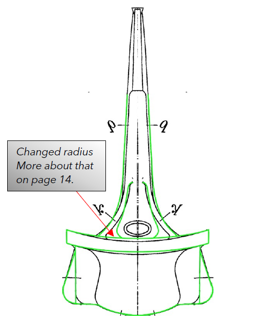
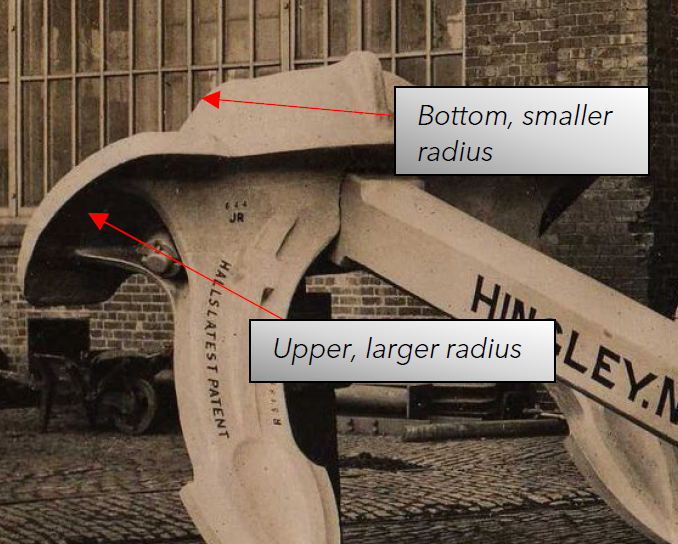
Curvature of the crown
The curvature of the anchor crown seems to differ in all drawings I have seen so far, and it is very difficult to interpret due to the angle and perspective of the pictures. I have concluded that radius of the bottom of the crown is larger and the upper radius is smaller, see below:
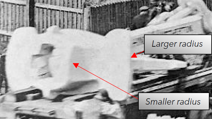
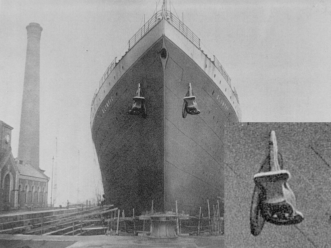
More images that show the curvature of the anchor, these shows it a lot better, in Figure 14.3 is an image of SS Olympic and you can see the side anchors in the image and the radius. The lower image is recognizable from earlier in the article.
Page 14 of 20
As images has shown, the bottom has a smaller radius than the upper part, the lower part of the model got the radius from figure 10.1 while I have increased the radius of the upper part to get it slightly flatter.
The Shank
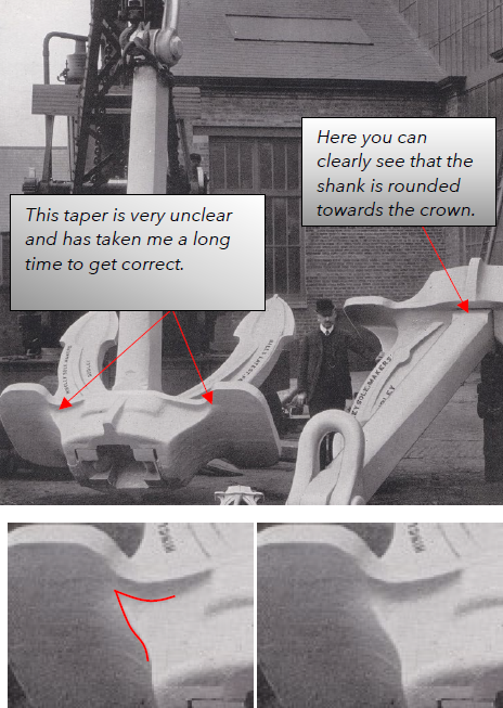
Unfortunately, there are no dimensions available for the shank, so everything is drawn with the help of pictures and sketches of the crown where the shank is partly included, see Figure 6.1. The shape is also quite difficult to interpret, but I have studied images for a long time to achieve my final shape. As main references I have used the following images:
Everything that is shown in the pictures is also included in the model, and I have studied the pictures carefully to try to incorporate these unique properties as accurate as possible.
Page 15 of 20
Summary
Using the facts and images available today, the model represents the Olympic class centre anchors very well and are as close to the real anchor as can be obtained without lifting the anchor from the wrecks to study them more carefully.
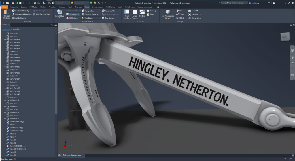
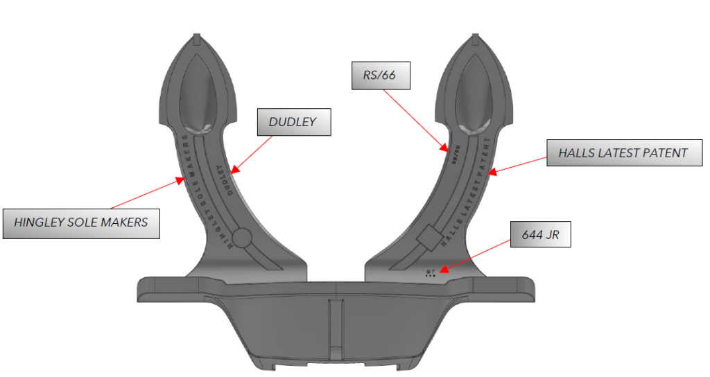
The model contains many free interpretations of form and will contain inaccuracy. The model should not be considered as an exact copy, but a very similar replication of the anchor. The lettering on the anchor is mainly based on figure 14.1 and 8.1, since it is sometimes difficult to see which characters are used, this is an interpretation by me and is as follows:
HALLS LATEST PATENT
HINGLEY SOLE MAKERS
DUDLEY
RS / 66
644 JR
Position of the lettering will be shown on the next page.
Improvements and corrections
I am happy to receive more information to improve/correct the model and update the article to get it more accurate. I have used all the information I have been able to access.
The following pages show all the components of the model.
Page 16 of 20
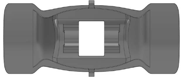
Crown Head [17.1]
(Color has been adjusted for better visibility)
Page 17 of 20
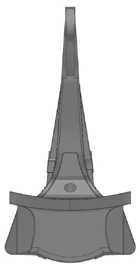
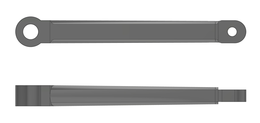
Shank [18.1]
(Color has been adjusted for better visibility)
Page 18 of 20
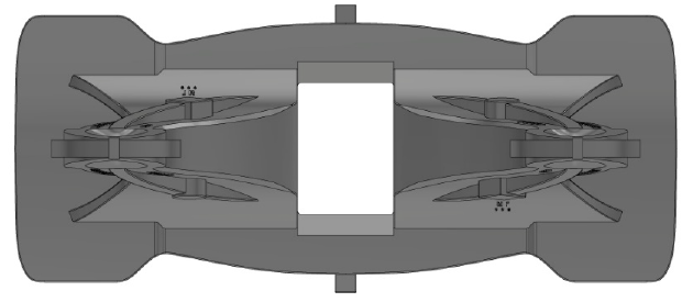
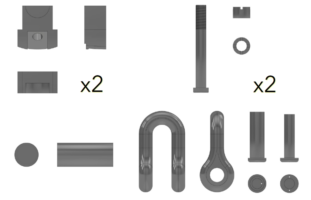
Fastening blocks, main bearing, bolts and shackle [19.1]
(Color has been adjusted for better visibility)
Page 19 of 20
Use and availability of the model
The model is not just created for me, it is meant to be used but not abused. Anyone who would like to use the model for their own projects can contact me, and I will help with the right type of files and model. The model may not be used for commercial use without my approval.
The files for the model will be distributed by me to those who want the model, to use it you need to specify where the model comes from in any publications. The model may not be posted for download by the recipient of the files.
Responsible for this article:
Joakim Amundsson
joakim@karlstabo.se
Update log:
2021.12.13 – Shackle bearing changed from hollow to solid based upon image 9.4 (Originally based on image 12.1)
Page 20 of 20